What is the logic signal current of a stepper motor?
What is the logic signal current of a stepper motor?
Stepper motors, often employed in precision control systems, are a critical component in a wide range of applications — from computer printers and CNC machines to robotic arms and space exploration vehicles. As with any electronic device, stepper motors operate on the basis of electrical signals. To comprehend their functioning, one must understand the logic signal current, which plays a key role in controlling the motor's operation.

Introduction to Stepper Motors
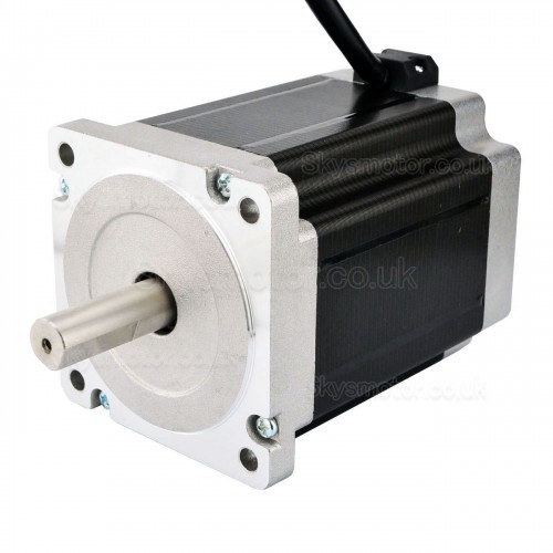
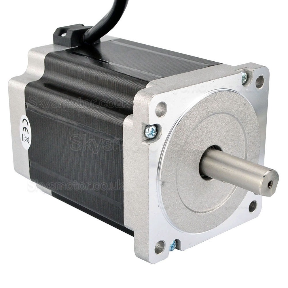
Before we delve into the specific topic of logic signal current, let's take a brief look at stepper motors. A stepper motor is a type of electric motor that moves in discrete steps, hence the name. It does this through a series of electromagnetic coils arranged in 'phases' that are energized in a specific sequence. Each step represents a precise angle of rotation, ranging from a few degrees to fractions of a degree.

Role of Logic Signal Current
The logic signal current in a stepper motor refers to the electrical current that is used to control the sequence of steps and the speed of the motor. The logic signals are digital and can be either "high" (usually 5V or 3.3V depending on the system) or "low" (usually 0V).
To elaborate, the logic signals are used to control the driver circuit of the stepper motor. The driver circuit is responsible for energizing the various phases of the motor in the correct sequence and polarity, which makes the motor shaft rotate. In most cases, the driver circuit is an integrated circuit (IC) that receives logic signals from a microcontroller or a computer.
The Working of Logic Signal Current
Different stepper motors use different types of logic signals. Some stepper motors require only two logic signals — a step signal and a direction signal. When the step signal changes from low to high (or high to low), the motor moves one step. The direction of the step (either clockwise or anticlockwise) is determined by the state of the direction signal.
More complex stepper motors might require additional logic signals like an enable signal (to turn the motor on or off), a reset signal (to reset the motor to a known state), or a sleep signal (to put the motor into a low-power state).
The current of the logic signals is usually quite small — often just a few milliamperes. This is because the logic signals are not used to drive the motor directly; instead, they are used to control the driver circuit. The driver circuit, in turn, controls the large currents (often several amperes) that drive the motor coils.
Importance of Logic Signal Current
The significance of the logic signal current lies in its role as the interface between the microcontroller (or computer) and the stepper motor. By changing the state of the logic signals, the microcontroller can control the motor's speed, direction, and position. This enables precise control of the motor, which is essential in many applications.
